CABLE TRAY MANUAL Based on the 2014 National Electrical Code Cable Tray Manual 2014 Cable Tray Manual B-Line series Cable Tray Systems MAN-1 Eaton Mark shown is the property of its respective owner. Cable tray laying to take care of necessary clearances for the fire proofing of structure.

Consultant Cad Drawings Equipment Cable Tray Layout Services In Whole World Id 3325849112
In the Conduit Layout Preferences worksheet select Automatically create.

. Instrumentation design course delivers 3D modeling 2D extraction Modifying equipment shapes Cable tray specification and Extraction of instrument location layout. As part of our ongoing commitment to customer support Legrands cable management ranges and Cablofil wire mesh cable tray are now integrated into the following plant design modeling systems. If not it will only act as a parallel earthing conductor PEC.
Vendor Drawings for PSV Control Valves Flow Meters Level Instruments Pressure Instruments Temperature Instruments etc. Fix the cable tray as. Solutions such as cable systems to the State Territory or Country where system design and engineering installation is to take place.
Single line diagram can be prepared when instrument cable schedules are available. Paneldes Raceway software is for construction engineers with electro-mechanical design and cable management requirements such as those designing plant cable raceway ductbank cable tray and cable ladder layout and cable routing. Cable Management 3D Modeling Tools.
Cable trays are open leaving the cables exposed to the environment. This is done through. Project management installation and postsale services.
What kind of electrical and instrument drawing can be found in fabrication of an oil and gas fabrication project. Following are the steps to be done for laying cables on wall mounted cable tray. To join two components together clamp or fix to walls ceilings or other supports covers and cable retainers Associated supports Bespoke supports for cable.
Hot lines and cold lines shall be kept apart in different groups on a tier. 6 Cable Ladder and Cable Tray Systems Including Channel support Systems and other Associated Supports Definitions and Abbreviations Accessory Component used for a supplementary function eg. Acceptance testing cable cable installation cable selection communication cable.
Instrument Layout and recommended cable tray routing drawing within battery limit Instrument installation drawing. For Construction Engineers with Electro-Mechanical Design Requirements. We can extract cable tray layout junction box layout instrument location layout bill of materials etc easily using 3D modeling software.
Generally the top tier is to be kept for Electrical cable trays if not provided in underground trench and Instrument cable ductstrays. Click OK and then enter an elevation in the Add Cable Trays dialog box. Piping and Instrumentation Diagram PID.
Where used these should have an adequate mesh for the frequencies in use and be properly earthed. Cable trays of metallic construction should be considered. 48 2384 ratings 3259 students enrolled.
The data files available are specifically for use with the relevant systems and as such cannot be used or converted. The design installation and protection of wire and cable systems in substations are covered in this guide with the objective of minimizing cable failures and their consequences. They are made with the guidelines of Instrument Location Layout and thus helps in grouping junction boxes.
List of alarm points with settings and ranges. Trays can be produced of strong steel wire for light-duty applications such as instrument signal cabling or network computer cabling or they can be made of steel or aluminum channel for heavy-duty applications such as electrical energy cabling. PDMS Plant Design.
Single triad shielded signal. E3D Everything 3D by Aveva. Click Preferences on the Properties palette.
Instrument wiring layout instrument air routing layout loop drawing jb layout cable schedule cable tray layout. Compatible with AutoCAD and Gstar-CAD. As I described in the above diagram specification for field instruments DCS Safeguarding systems instrument standard drawing has to be completed prior to prepare the requisitions and inquiry report for field instruments cables etc.
Subcontractor shall submit actual cable tray drawing after installation for As-built. In the Cable Tray Layout Preferences dialog box on the Routing tab select Automatically create riser at new Elevation. Instrument Wiring Layout.
The tray will effectively become screen or enclosure for the cables if it has a lid fitted. This only an overview and few drawing samples for who wants to know about a project fabrication -construction specially. Instrument location plan drawing can be started to.
Single pair shielded thermocouple extension cables shall be used between thermocouple head and junction boxes transmitters local control panel mounted instruments. Prysmian focuses on continuous product innovation and on achieving a competitive edge by focusing on research and development. Material take-off for instrument cables cable trays tray supports etc.
The popular list of instrumentation modeling software is as follows. Instrument Air Routing Layout. The size length and intervals of the support to be as per the specification standards number of cables and size of the cable.
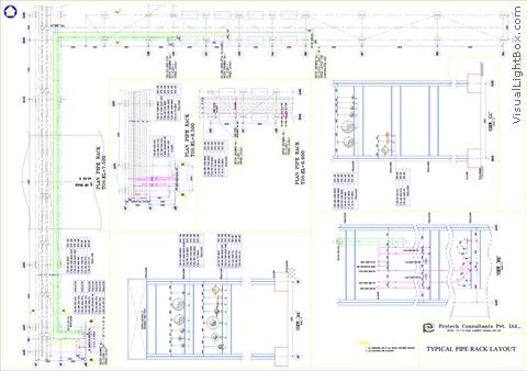
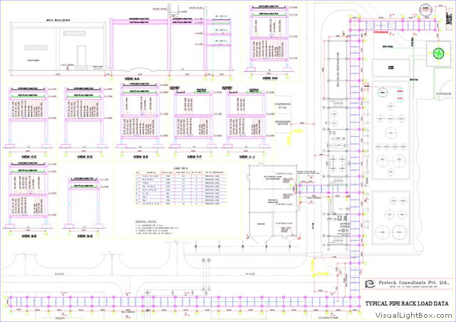
Instrument Tray Layout is the drawing that shows the location of junction boxes instrument air header local panel the instrument tray routing in the plan view. IO List for DCS. Intermediate support for upper tray required on piperacks over 6096mm wide.
Field cut cable tray length as required. Process data sheets for Equipments. The separation barrier was confirmed to be missing by visual inspection of the cable tray.
This cable tray support system drawing has Isometric view and cross-sectional view. Click in the Add Cable Trays dialog box. All installation requirements and tolerances shall be in accordance with the technical specification the latest construction drawings and the applicable documents.
InstruCalc Smartplant Instrumentation INTools. The final branch cable tray route shall be decided by subcontractor Field Engineer in accordance with the site condition. - IEEE Guide for the Design and Installation of Cable Systems in Power Generating Stations ANSIIEEE Std 422-1986 Revision of IEEE Std 422-1 977 Published by The Institute of Electrical and Electronics Engineers Inc 345 East 47th Street New York NY 10017 USA April 4 1986 SH10447 WITHDRAWN.
Vertical cable tray elbows at the top of runs should be supported at the joint on each end. INSTRUMENT CABLES This specification covers the requirements for instrument signal cables thermocouple extension cables RTD cables and power control cables. Install cable tray support using a pre-fabricated flange or GI channel.
Material take-off for field instrument installation hardware. Instrument cable wiring schedule. Showed that the instrument cables were routed through a divided traybut plant cable tray layout drawins indicated that a separation barrier was not installed in the cable tray.
Typical Instrument Cable Tray Layout Pdf Pdf

Detail Engineering Protech Consultants Pvt Ltd

Cad Drawing Electrical Cable Tray Layout Plan Legend

Cable Tray Installation Free Cad Block And Autocad Drawing

Electricveda Com Method Statement For Installation Of Cable Tray Or Trunking
Detail Engineering Protech Consultants Pvt Ltd
Detail Engineering Protech Consultants Pvt Ltd

Sample Drawings Of Power Distribution Projects Equipment Cable Tray Layout Services Consultants From Kolkata
0 comments
Post a Comment